Inefficiently solving GoogleCTF 2021 with Verilog (ModelSim)
Published on
Table of Contents
I unfortunately did not solve this during the competition period, but mildly obsessed over this for about a week after the competition. Here’s how I lost way too many hours of sleep.
TL;DR - Realise this was all just one big digital logic circuit, recognise the different logic gates and connections, build it all in Verilog, solve with some ModelSim bruteforcing, and get enough sleep.
Introduction
The challenge provides us with a zip file containing a python script that takes in some data (level1 / level2) to build the challenge. run.sh just serves as an easy way to progress from level1 to level2.
Level 1
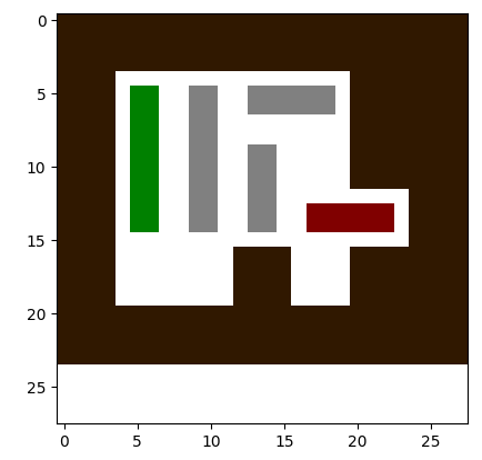
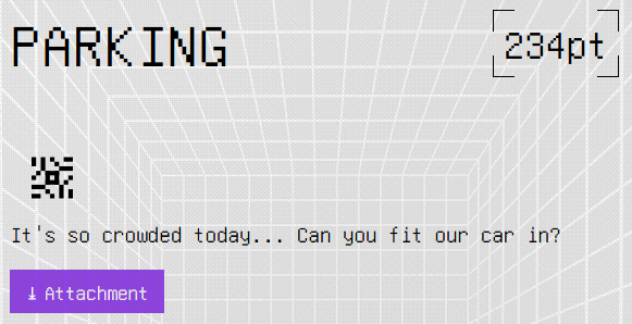
Well this doesn’t seem too bad… We’re told (in the command line) that the goal is to simply move the red car from its original position, and the green block will encode the flag. Just shift the blocks around and it’s as simple as that. Bring on level 2!
Level 2
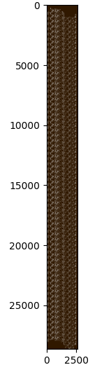 Well… I can almost see my life flashing before my eyes. Solving this through the matplotlib graph it creates would be a pain (especially given that it took about a minute for matplotlib to load the graph itself). Clearly, we need to analyse how it’s getting the map.
Analysis
Let’s take a look at the game.py
script first.
A quick skim through the code reveals that it parses the data determined by the level1/level2 file, builds the world’s worst carpark, and allows for the user to click to move cars. There are a few important things to note:
- First, the red block has “movable” attribute as -2, and if the script detects that the block has moved from its original position, the
printflag()command is called. - Second, it adds the cars that have “moveable” attribute equal to -1 to a flagblocks array. These cars are the green blocks that encode the flag (in binary).
- On top of that, the each car represents each bit of the flag, and is determined by whether the car has to move from its original position (moved = 1, otherwise 0).
- And finally, the bits of the flag are separated into bytes (8 bits) and reversed before being converted to ASCII and printed.
With all those in mind, we have a good enough overview of what we need to do: Determine which green blocks need to be moved in order for the red block to move.
Now the hours of “fun” begin.
Diving deeper
Whilst we have a general idea of how everything works, how in the world do we apply it here? Most importantly, where in the world are the green and red blocks?
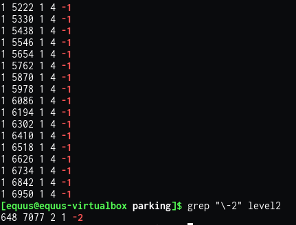 Doing a quick grep on the level2 file (based on -1 == green block, and -2 == red block), we can see that there are a lot of green blocks (64 in fact) all in a vertical line, and one singular red block in a tiny corner. We know this, as the python script parses the file info as (x,y,w,h,movable). On top of that, the green blocks are added to the flagblocks array from top to bottom, meaning the top most green block represents bit 0, and the bottom most green block represents bit 63.
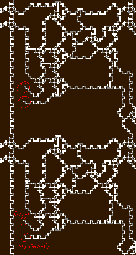
Time to zoom in even more! Luckily the python script uses PIL to save the graph as a png, so we won’t have to deal with the 10 seconds it takes for matplotlib to zoom in.
 The scariest thing about this, is that this is only a small section of the whole bigger picture. Anyone hoping to somehow solve this by hand ought to be reported for insanity.
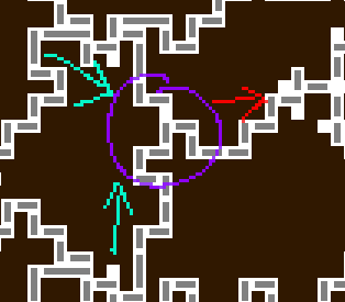
 Working backwards from the red block, it’s clear that the vertical line of grey blocks must move. But we seem to hit a jam where the top circled region is. In order for the grey blocks to move up, the long skinny grey block, as well as the shorter block (inside the circled region) must both move. Looking at this, if we consider the two arrows pointing toward the circle as inputs, and the arrow pointing away from the circle as outputs, this is starting to look like an AND logic gate! We will consider the inputs as whether there’s “a flow/gap” coming in. So if the cars can move then it’ll be a 1, otherwise it’s 0.
This can get confusing, as the gap moves in the opposite direction to the cars, but with enough annotating and imagination, we might be able to figure this one out.
A step back
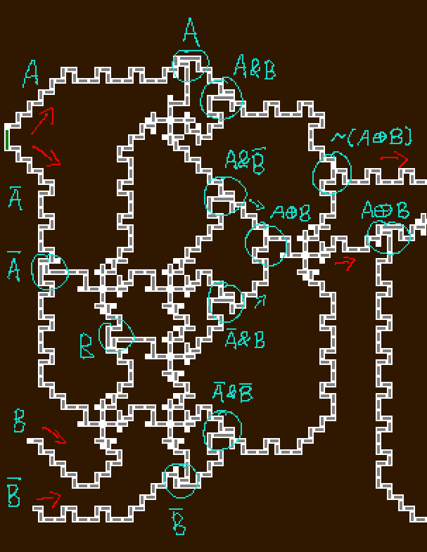
 Ignoring the questionable colour choices I’ve made, if we step back to look at the bigger picture, it’s clear there are two types of “blocks” just repeated over and over. Block A seems to be a 4 input, 2 output block of some sort, and B seems to be a big 4 input, 4 output block. This makes analysis so much easier, as we only need to determine the behaviour of two blocks. So let’s get started.
Junction types
But before we jump in on analysing each block, we must first identify all the different types of “junctions”. These junctions can be a real nuisance, but they help simplify the blocks down to a simple logic gate. Although difficult to determine at first, it’s possible to figure out each if we know which way the traffic (gap) flows, and the output behaviour based on different inputs. I’ll be giving them random names that are definitely not their official names, but I do like to pretend they form some superhero team (a digital logic version of The Avengers?).
The And
 Just your regular AND gate.
Th(e) Or
 A proud member of The Avengers. Also happens to be a classic digital logic gate.
The Criss Cross
 These allow for two wires to cross over each other without affecting each other. In this case, the vertical flow has no effect on the horizontal flow.
The Splitter
 Takes in one input, and splits it into two: essentially clones an input.
Block A
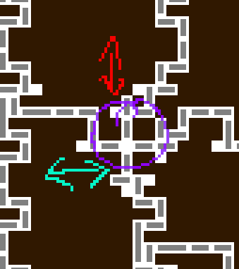
 If we let the flow of the gap go from left to right in this image (following the rough direction of the red arrows), we can simplify this block down to a simple logic circuit. As it turns out, the “4 inputs” can be treated as 2 inputs, as one is always the reverse of the other. Even better, the “2 outputs” can also be seen as only 1 output, as
 not(A xor B) is the opposite of A xor B.
Block B
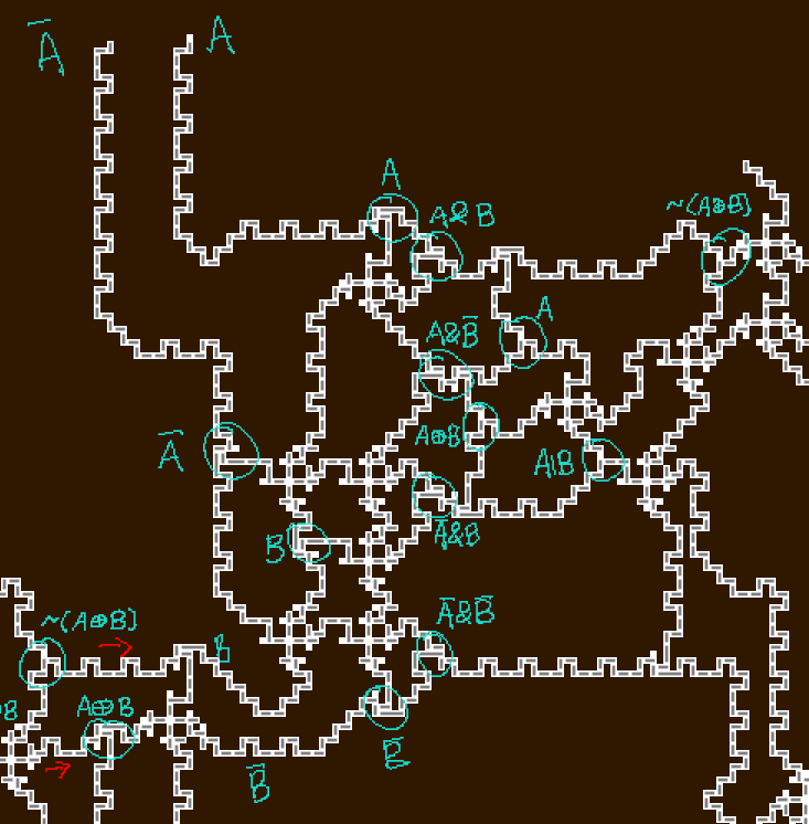 The same sort of logic can also be applied to block type B. This block can be modelled as a 2 input, 2 output logic gate, where the top output is
 not(A xor B) and the bottom is A or B.
Oh yeah, it’s all coming together
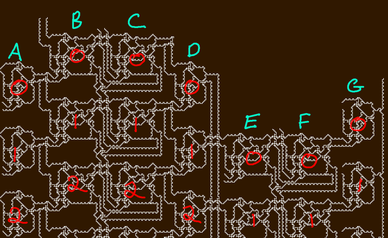 Now to link all these different blocks together. Based on the above labels (each row is assigned an index between 0 and 63, and each column is a letter between A and G), we have the following connections:
A:
inputs: car, in1
outputs: A[i]

B:
inputs: A[i-1](1 if i==0), A[i]
outputs: B1[i], B2[i]

C:
inputs: B1[i], C2[i-1]&B2[i-1] (1 if i==0)
outputs: C1[i], C2[i]

D:
inputs: C1[i], C1[i+1] (1 if i==63)
outputs: D[i]

E:
inputs: D[i+1] (D[0] if i==63), in2
outputs: E1[i], E2[i]

F:
inputs: E1[i], E2[i-1]&F2[i-1] (1 if i==0)
outputs: F1[i], F2[i]

G:
inputs: in3, F1[i]
outputs: G[i]
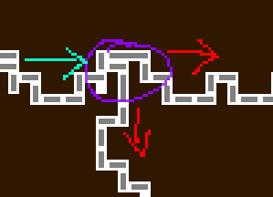
Rogue Inputs
 There seem to be extra unknown variables in the above connection rules. Clearly
 car represents the green block inputs, but what are in1, in2, and in3? As it turns out, some blocks have some cheeky external input, as shown in the example above. When modelling the entire circuit, I will only take into account the top of the inputs (in the example above, the top block will have 0 as its extra input, and the bottom block will have 1 as its extra input).
Building with Verilog
Very smart CTF professionals would resort to Z3 or any other SMT/SAT solver. So naturally I decided to turn to Verilog instead.
Verilog is a hardware description language that can be used to model electronic systems. In this case, we can use it to describe the digital circuit we’re given, and then hopefully find a way to determine the correct input in order to make that red block move. Given that each block can be modelled as a logic gate, we can treat each block as its own module, where it has 2 inputs, and either one or two outputs.
module lil_xor(input A,B, output out_xor);
	assign out_xor = (A==B);
endmodule

module big_boi(input A,B, output out_eq,out_or);
	assign out_eq = (A==B);
	assign out_or = A | B;
endmodule
lil_xor is the 2 input 1 output block (its name is misleading, but let’s pretend I named it correctly), and big_boi is the bigger cousin, with 2 inputs and 2 outputs.
Now to implement all the connections with some Verilog magic.
module parking(input [63:0]in,output [63:0]out);
	reg [0:63] in1 = 64'b1000010011111100010010101000010010000100111111000100101010000100;
	reg [0:63] in2 = 64'b0001001100110111000100110011011100010011001101110001001100110111;
	reg [0:63] in3 = 64'b1010111111011110001100101110101001010101011110100101011100000111;
	wire [63:0]out1;
	// starting 64 car blocks - contains fixed input
	genvar i;
	generate
		for (i = 0; i < 64; i=i+1) begin : ricky
			// invert car input (0 means A = 1, 1 means A = 0)
			lil_xor test(~(in[i]),in1[i],out1[i]);
		end
	endgenerate

	// second block
	wire [63:0]out2, out3;
	generate
		for (i=0; i < 64; i=i+1) begin : bobby
			if (i==0) big_boi test(1'b1,out1[i],out2[i],out3[i]);
			else
				big_boi test(out1[i-1],out1[i],out2[i],out3[i]);
		end
	endgenerate

	// third block
	wire [63:0] out4, out5;
	generate
		for (i=0;i<64;i=i+1) begin : robby
				if (i==0) big_boi test(out2[i],1'b1,out4[i],out5[i]);
				else big_boi test(out2[i],out5[i-1]&out3[i-1],out4[i],out5[i]);
		end
	endgenerate

	// fourth block
	wire [63:0] out6;
	generate
		for (i=0;i<64;i=i+1) begin : bibby
			if (i==63) lil_xor test(out4[i],1'b1,out6[i]);
			else lil_xor test(out4[i],out4[i+1],out6[i]);
		end
	endgenerate

	// fifth block - contains fixed input
	wire [63:0] out7, out8;
	generate
		for (i=0;i<64;i=i+1) begin : timmy
			if (i == 63) big_boi test(out6[0],in2[i], out7[i],out8[i]);
			else big_boi test(out6[i+1],in2[i],out7[i],out8[i]);
		end
	endgenerate

	// sixth block
	wire [63:0] out9, out10;
	generate
		for (i=0;i<64;i=i+1) begin : tommy
			if (i==0) big_boi test(out7[i],1'b1,out9[i],out10[i]);
			else big_boi test(out7[i],out8[i-1]&out10[i-1],out9[i],out10[i]);
		end
	endgenerate

	// seventh block - contains fixed input
	wire [63:0] out11;
	generate
		for (i=0;i<64;i=i+1) begin : bob
			lil_xor test(in3[i], out9[i], out11[i]);
		end
	endgenerate
	assign out = out11;
endmodule
Et voilà! This is essentially the Verilog version of the connection equations (where A-G are blocks 1-7 respectively). Just a few strange Verilog things to note:
[0:63]means the most significant bit (MSB) is bit #0, and least significant bit (LSB) is bit #63, whereas[63:0]means MSB is bit #63, and LSB is bit #0genvaris like a regular integer in programming languages, but in Verilog,genvaris required so that it can be used to instantiate multiple instances of the same module, because regular integers just aren’t good enough for verilog- the for loops in generate blocks must be named, so that Verilog (simulators) can differentiate between each instance of the module
- obviously ricky, bobby, robby, bibby, timmy, tommy and bob are fantastic names for these
The in1, in2, and in3 were obtained by scrolling through the map and noting down 1’s and 0’s, whilst simultaneously praying that no mistakes were made during transcription.
Solving with ModelSim
Now comes the part that shouldn’t have taken over a week to figure out and get working properly, but did nonetheless.
Coming up with some ideas
Idea 1: Use Quartus’ RTL viewer to simplify the circuit and give us a solution
I had been using Quartus (and hence Verilog + ModelSim) for a semester for uni, so my mind went straight to “how can I justify the hours I spent reading Verilog and Quartus documentation”. Despite this, I had completely forgotten that Quartus comes with an RTL viewer that essentially gives a high level representation of the digital circuit (i.e. using logic gates). On top of that, it’s also smart enough to simplify more complicated circuits. So thanks to a nudge from a Verilog Veteran, I decided to give it a crack.
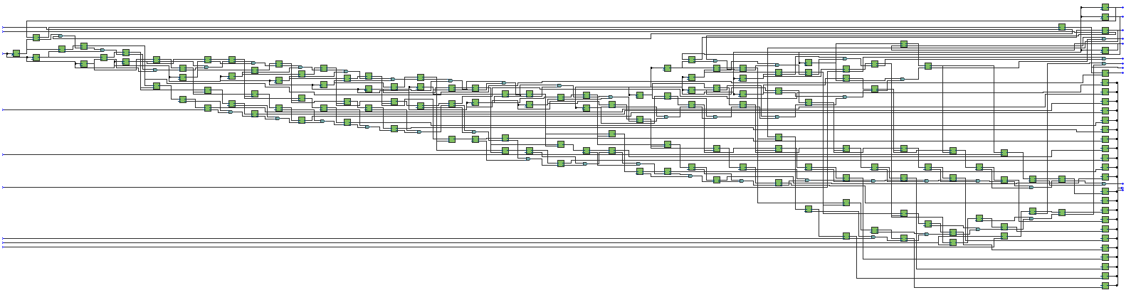 Quartus has let me down once again. After many attempts to break the circuit down to allow Quartus to simplify, there was no way for it to give me a small enough circuit to easily solve. Keep in mind, the above image was just page 1 of 3.
With Quartus unable to help me with this, I decided to turn to ModelSim.
Quartus has let me down once again. After many attempts to break the circuit down to allow Quartus to simplify, there was no way for it to give me a small enough circuit to easily solve. Keep in mind, the above image was just page 1 of 3.
With Quartus unable to help me with this, I decided to turn to ModelSim.
ModelSim is lovely, in that it simulates Verilog modules given a testbench. It also has a bunch of nice graphical features (waveforms mainly), but we’ll probably just stick with the console/terminal outputs for this.
Now we just need to write a testbench that will solve the problem for us. In this case, we need to determine what 64 bit input will give us the output of 64 bits of 1’s.
Idea 2: Bruteforce all 64 bits
Although technically possible, ModelSim is unfortunately way too slow to bruteforce 64 bits. By the time it finds the solution, we’ll all probably be ruled over by giant kittens that shoot lasers out of their eyes, so that’s a no go.
Idea 3: Knowing that the flag is ASCII, bruteforce 56 bits, since we know that every 8th bit is a 0
This certainly reduces the amount of time needed to bruteforce, however, whilst we probably won’t be ruled by laser shooting kittens by the time it finishes, it will probably take longer than the average lifespan of a human. I don’t know about you, but I’d like to be alive before it finishes.
Idea 4: Bruteforce n bits at a time, where n is a reasonable number of bits that can be bruteforced
Now this is more like it. Now we just need to find the sweet spot of a reasonable number. Since each bit of the input affects the output of its neighbouring bits (i.e. changing bit 5 affects the output of bit 6), and it’s also “cyclic” (i.e. bit 0 affects the output of bit 63 and vice versa), we should probably try and figure out just how big its influence is.
Looking at the Verilog implementation of the digital circuit, we can see that some inputs depend on outj[i-1] or outj[i+1]. Since the output blocks “cascade” (output of first block flows onto second, which flows onto the third block etc.), we can determine just how many neighbours a change in bit i affects.
 The above shows roughly how a change in a bit affects the neighbours. Blocks 2, 3 and 6 rely on the output of a block on the previous row - e.g. Row 5 block 2 relies on the output of Row 4 block 1. On the other hand, blocks 4 and 5 rely on the output of a block on the next row - e.g. Row 5 block 4 relies on the output of Row 6 block 3. Note how block j on row i only relies on block j-1 (and never block j+1).
 What all this essentially means is that if we’re working from index 0 to index 63, if the output bits from 0 to m are all 1’s, then bits 0 to m-3 are all correct.
If we’re working from index 63 to index 0, and the output bits are all 1’s from 63 to n, then that means all bits from 63 until n+2 are correct.
So the plan? Bruteforce 8 bits from left to right, and 8 bits from right to left, with some extra bits as a buffer (based on the above revelations). This means we’ll be bruteforcing a maximum of 21 (8+8+3+2) bits at a time. ModelSim only takes a few seconds to do bruteforce 21 bits, so we’re good to go.
Writing the testbench
`timescale 1ns/1ps

module test;
  reg [63:0] in;
  wire [63:0] out;
  parking test(in,out);
  reg [21:0] i,j,k;
  reg [7:0] verify;
  reg [63:0] flag=64'b0;
  initial begin
    for (j=0;j<3;j=j+1) begin
      // brute force first and last few bits
      for (i=0;i<2**21;i=i+1) begin
        in = flag;
        in[63-(j*8) -:10] = i[20:11];
        in[j*8 +: 11] = i[10:0];
        #10;
        // check out bits based on observed patterns
        if (out[63-(j*9) -: 7] == 7'b111_1111 && out[j*8 +: 6] == 6'b111_111) begin
          // verify that every 8th bit is a 0, because ASCII
          for (k=0;k<8;k=k+1)
            verify[k] = ~(in[(k+1)*8-1]);
          if (&verify) flag = in;
        end
      end
    end
    // final 16-ish bits
    for (i=0;i<2**16;i=i+1) begin
      in = flag;
      in[39:24] = i[15:0];
      #10;
      if (&out) begin
        flag = in;
        // Victory display
        $display("After too many hours, the flag has been obtained!!!\n%b",flag);
      end
    end
  end
endmodule
We only need to bruteforce 21 bits at a time 3 times, since that will already give us 48 bits of the flag (we take 16 out of the 21 bits each time). The rest can be done with a smaller range. There are delays (#10;) just in case some changes take a little longer to propagate through the circuit.
 At long last, we get what should hopefully be the bits of the flag. Good news is, that it only took 30 seconds! Now to put them in the correct order, and finally, after all these sleepless days, get the flag.
flag = b"CTF{"
while bits:
    byte, bits = bits[:8], bits[8:]
    flag += bytes([ int(byte[::-1], 2) ])
flag += b"}"

print(flag)
Looking at this specific chunk of the print flag function in game.py gives all the details needed to get the flag from the bits obtained from ModelSim.
 So doing just that (then throwing it around
 CTF{}), we get our flag!
Flag: CTF{2TheBr1m}
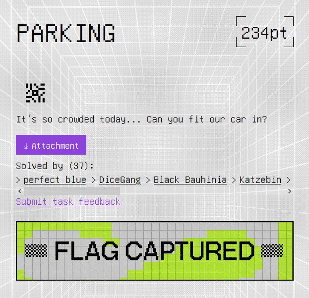 A sight I wish I saw during the competition period.